
How to Design With PEM Hardware

Advantages of using PEM Hardware
PEM hardware offers a time-efficient solution for incorporating nuts, studs, or standoffs into sheet metal parts. By utilizing PEM hardware in your sheet metal parts, you reduce part count and enhance thread strength, streamlining the assembly process compared to tapping, or welding components to your sheet metal parts, which can reduce dimensional accuracy.
Traditional tapping often demands thicker parts to provide adequate thread strength, resulting in increased weight and higher costs. In contrast, PEM nuts allow the use of thinner materials while maintaining superior thread strength. This keeps parts lightweight and contributes to cost savings, making it a cost-effective and efficient alternative.
Designing around PEM Hardware
Since Onshape is our recommended platform for designing laser-cut sheet metal parts, this guide will use examples from the Onshape interfaces. However, concepts should be general enough to transfer to your CAD package of choice.
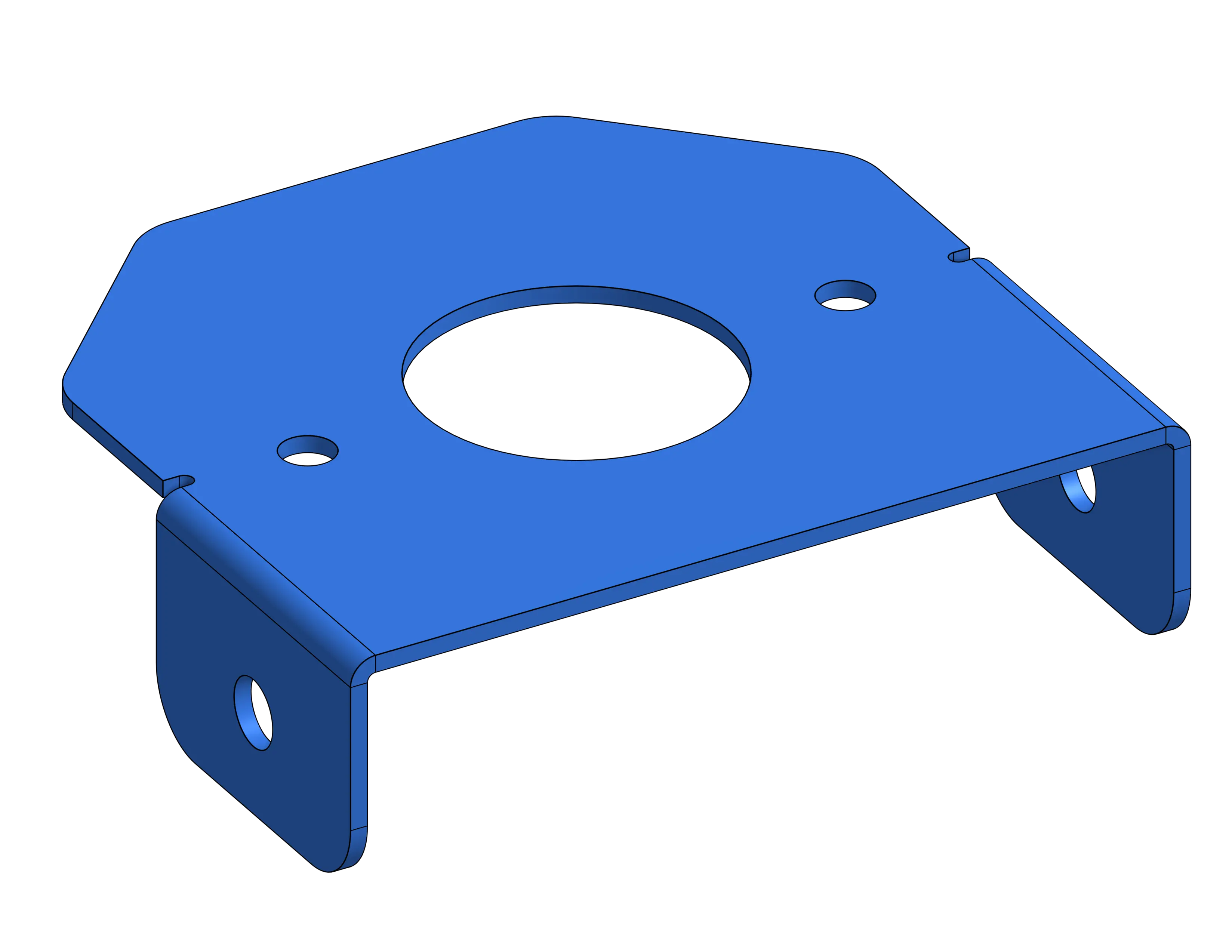
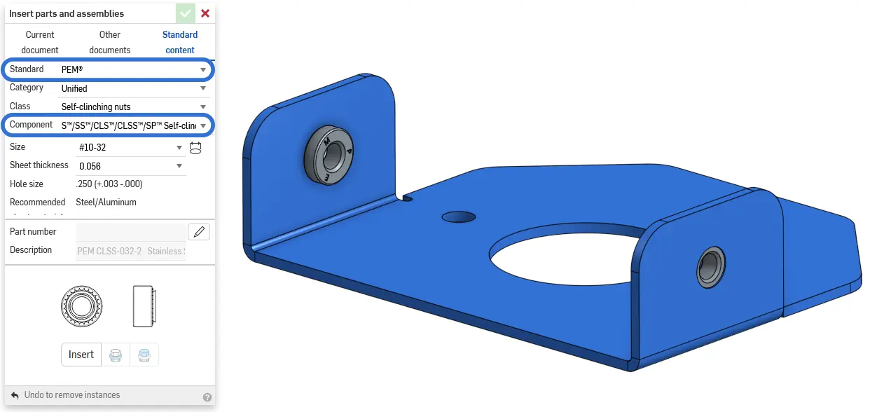
This bracket is made out of thin .0625” aluminum, making it a poor choice for traditional tapping. Adding PEM hardware inside of Onshape is very simple using the Standard Content Library. Just select PEM in the “Standard” drop-down, and make sure you have the correct component selected. To make sure the component has the correct dimensions reference the Fabworks hardware documentation
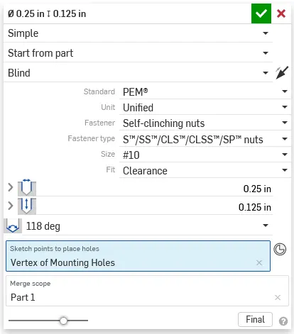
The Fabworks laser cutting service resizes holes labeled for hardware automatically, but if you want parody between your model and the final part Onshape’s hole tool has presets for PEM hole sizes. If you are not using Onshape or want to integrate these dimensions into your part sketches you can reference the Fabworks documentation on hardware.
Once you have your model completed you can export the part as a STEP file and import it into the Fabworks laser cutting service. If you need help exporting your model you can look at the step file exporting guide.
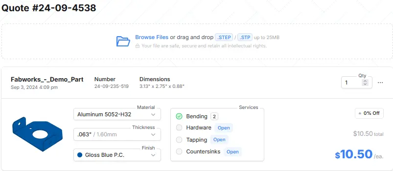
Once into the interface open the hardware configuration interface to get started adding hardware to your part.
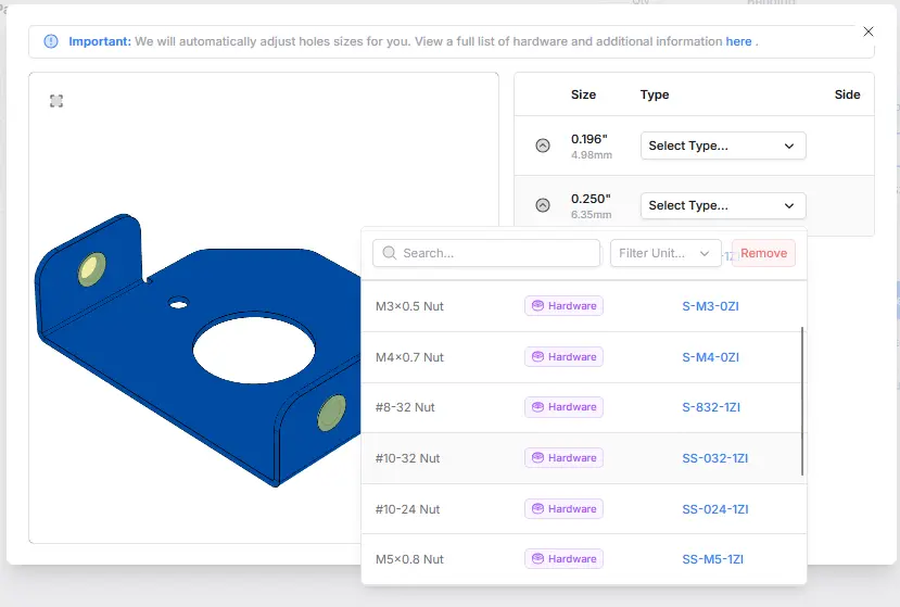
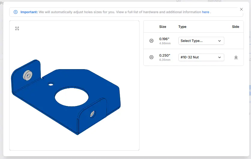
Once you select your hardware type you will notice the 3D visualization update to match the PEM hardware you selected. Make sure you have the PEM hardware side so that it matches your original model.
Additional Support
If you have difficulty uploading or configuring hardware for your part, our support team is happy to help.
Order Sheet Metal Parts.
Upload your STEP file for an instant laser cutting quote. Quote in seconds, order in minutes, receive parts in days.